Tutorial - Using the 0.96" 128 x 64 Graphic I2C OLED Displays with Arduino
Your new 0.96" 128 x 64 Graphic I2C OLED display is a compact and useful display, that require a small amount of time to get working with your Arduino or compatible board.
The purpose of this guide is to get your display successfully operating with your Arduino, so you can move forward and experiment and explore further types of operation with the display.
This includes installing the Arduino library, making a succesful board connection and running a demonstration sketch. So let's get started!
Connecting the display to your Arduino
The display uses the I2C data bus for communication, and is a 5V and 3.3V-tolerant board.
Arduino Uno to Display
GND ---- GND (GND)
5V/3.3V- Vcc (power supply, can be 3.3V or 5V)
A5 ----- SCL (I2C bus clock)
A4 ----- SDA (I2C bus data)
I2C pinouts vary for other boards. Arduino Leonard uses D2/D3 for SDA and SCL or the separate pins to the left of D13. Arduino Mega uses D20/D21 for SDA and SCL. If you can't find your I2C pins on other boards, email support@pmdway.com for assistance.
Installing the Arduino library
To install the library - simply open the Arduino IDE and select Manage Libraries... from the Tools menu. Enter "u8g2" in the search box, and after a moment it should appear in the results as shown in the image below. Click on the library then click "Install":

After a moment the library will be installed and you can close that box.
Now it's time to check everything necessary is working. Open a new sketch in the IDE, then copy and paste the following sketch into the IDE (you may find the "view raw" link at the end useful):
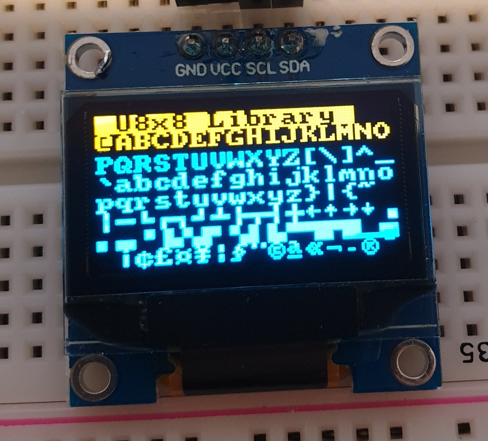
Your display should go through the demonstration of various things as shown in the video below:
By now you have an idea of what is possible with these great-value displays.
Now your display is connected and working, it's time to delve deeper into the library and the various modes of operations. There are three, and they are described in the library documentation - click here to review them.
Whenever you use one of the three modes mentioned above, you need to use one of the following constructor lines:
U8G2_SSD1306_128X64_NONAME_F_HW_I2C u8g2(U8G2_R0, /* reset=*/ U8X8_PIN_NONE); // full buffer mode
U8X8_SSD1306_128X64_NONAME_HW_I2C u8x8(/* reset=*/ U8X8_PIN_NONE); // 8x8 character mode
U8G2_SSD1306_128X64_NONAME_1_HW_I2C u8g2(U8G2_R0, /* reset=*/ U8X8_PIN_NONE); // page buffer mode
Match the mode you wish to use with one of the constructors above. For example, in the demonstration sketch you ran earlier, we used the 8x8 character mode constructor in line 14.
Where to from here?
Now it's time for you to explore the library reference guide which explains all the various functions available to create text and graphics on the display, as well as the fonts and so on.
These can all be found on the right-hand side of the driver wiki page.
If you have a problem with your display from PMD Way, please email support@pmdway.com for technical and order support.
And to keep up to date with interesting news, tutorials offers and new products - interact with us on facebook, instagram, and twitter.