Tutorial - Using the 0.96" 80 x 160 Full Color IPS LCD Module with Arduino
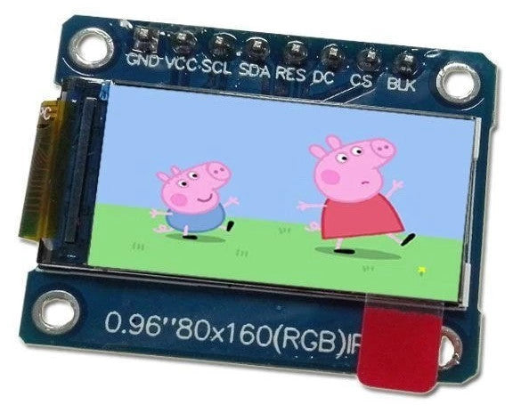
Your new 0.96" 80 x 160 Full Color IPS LCD Module is a compact and useful display, that require a small amount of time to get working with your Arduino or compatible board.
The purpose of this guide is to get your display successfully operating with your Arduino, so you can move forward and experiment and explore further types of operation with the display. This includes installing the Arduino library, making a succesful board connection and running a demonstration sketch.
Although you can use the display with an Arduino Uno or other boad with an ATmega328-series microcontroller - this isn't recommended for especially large projects. The library eats up a fair amount of flash memory - around 60% in most cases.
So if you're running larger projects we recommend using an Arduino Mega or Due-compatible board due to the increased amount of flash memory in their host microcontrollers.
Installing the Arduino library
So let's get started. We'll first install the Arduino library then move on to hardware connection and then operating the display.
(As the display uses the ST7735S controller IC, you may be tempted to use the default TFT library included with the Arduino IDE - however it isn't that reliable. Instead, please follow the instructions below).
First - download the special Arduino library for your display and save it into your Downloads or a temp folder.
Next - open the Arduino IDE and select the Sketch > Include Library > Add .ZIP library option as shown below:

A dialog box will open - navigate to and select the zip file you downloaded earlier. After a moment or two the IDE will then install the library.
Please check that the library has been installed - to do this, select the Sketch > Include Library option in the IDE and scroll down the long menu until you see "ER-TFTM0.96-1" as shown below:

Once that has been successful, you can wire up your display.
Connecting the display to your Arduino
The display uses the SPI data bus for communication, and is a 3.3V board. You can use it with an Arduino or other 5V board as the logic is tolerant of higher voltages.
Arduino to Display
GND ----- GND (GND)
3.3V ---- Vcc (3.3V power supply)
D13 ----- SCL (SPI bus clock)
D11 ----- SDA (SPI bus data out from Arduino)
D10 ----- CS (SPI bus "Chip Select")
D9 ------ DC (Data instruction select pin)
D8 ------ RES (reset input)
If your Arduino has different pinouts than the Uno, locate the SPI pins for your board and modify as appropriate.
Demonstration sketch
Open a new sketch in the IDE, then copy and paste the following sketch into the IDE (you may find the "view raw" link at the end useful):
Once you're confident with the physical connection, upload the sketch. It should result with output as shown in the video below:
Now that you have succesfully run the demonstration sketch - where to from here?
The library used is based on the uTFT library by Henning Karlsen. You can find all the drawing and other commands in the user manual - so download the pdf and enjoy creating interesting displays.
If you have a problem with your display from PMD Way, please email support@pmdway.com for technical and order support.
And to keep up to date with interesting news, tutorials offers and new products - interact with us on facebook, instagram, and twitter.