A Configurable Op Amp Lab on a PCB
from hackster.io
As outlined here, Microchip’s AVR DB family of chips contain a very interesting feature: three configurable op amps. These can be used separately, or linked together for advanced signal conditioning, which would be an exciting possibility for reducing a project’s BOM size. To experiment with it, David Johnson-Davies of Technoblogy came up with the Pocket Op Amp Lab earlier this year.
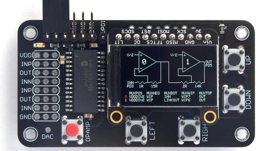
This device was originally constructed on a breadboard, based on an AVR128DB28 microcontroller. Its user interface consists of an Adafruit 240x135 color TFT display and four pushbuttons, which are routed to the processor itself. A variety of setup options are available, which dynamically update as you manipulate them. You could, for example, change an amplifier’s gain, and hear the effects in real-time.
Johnson-Davies also recently published a Pocket Op Amp Lab Cookbook to show what you can do with the gadget, and has now transferred it to a PCB version for an easy, portable, and self-contained tool. This board features a new user-defined button, and there are six op amp IO, as well as ground and VDD pins broken out and ready to use. To hold the display, there’s a clever offset arrangement of pins to keep it in place, or you can solder it on for a permanent solution.In whatever format you choose, this system looks like a great way to experiment with the AVR DB series from Microchip — and op amps in general!

Leave a comment