Recreating a Roadside Speed Sign Using an Arduino Nano and Doppler Radar
from hackster.io
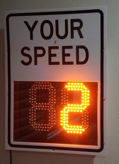
At any given moment while driving along a road, you've probably encountered one of these signs. Their large, contrasting text really stands out and grabs your attention, and the bright digits show your speed in almost any weather condition.
If a car's speed is above the limit the sign will being to flash rapidly to encourage the car to slow down a bit.
These types of signs take advantage of the Doppler effect, which describes how a wave bouncing off of an approaching object will increase in frequency the closer it gets, whereas an object getting further away will decrease in frequency.By sending out a series of quick pulses in rapid succession, a very accurate speed value can be obtained and thusly displayed on the sign.
One maker, John McNelly, wanted to recreate the look and feel of the radar sign using his own custom components, which is how he came up with his Arduino Radar Speed Sign project.McNelly's project works in much the same way as a commercially-available speed sign, with just a few small differences. He chose to use an HB100 Doppler module and pre-amplifier circuit to convert object's in its way to a square wave that the Arduino Nano can understand.
The HB100 generates and transmits a 10.525GHz signal that bounces off of an object (such as a car or person) and is then picked up by a receiver.
The Doppler shift is then determined by subtracting the incoming wave's frequency from the one it sent out, therefore calculating the speed.
There is a simple pre-amplifier circuit that takes the signal coming from the radar module and converts it into a square wave from a sine wave using two stages of capacitors, resistors, and op-amps.
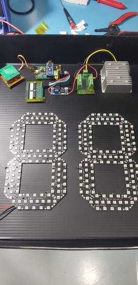
With a way to measure speed figured out, it was time for McNelly to work on the display portion. His design uses seven distinct "segments" that each contain 18 bright, amber LEDs rather than a single one in a normal seven-segment display.
Power is conveniently distributed over a pair of 12V rails that are located on the edges of each segment. To control everything, a single 74HC595 SPI shift register is used on each digit to control which segment is active and when.
Most of the circuit was placed onto a series of perf boards, including the Arduino Nano, the pair of shift registers, and the Doppler radar module.
McNelly's then painstakingly soldered the 252 total LEDs (18 per segment x seven segments per digit x two digits!), along with the MOSFETs and control circuitry, to the seven-segment displays.
All of this was then assembled into a custom "Your Speed" sign that looks just like the real thing.
As seen in McNelly's YouTube video below, the radar sign was able to pick up the runner's speed accurately, with him achieving a high score of 16mph. You can see the code and design files here on GitHub.


Leave a comment