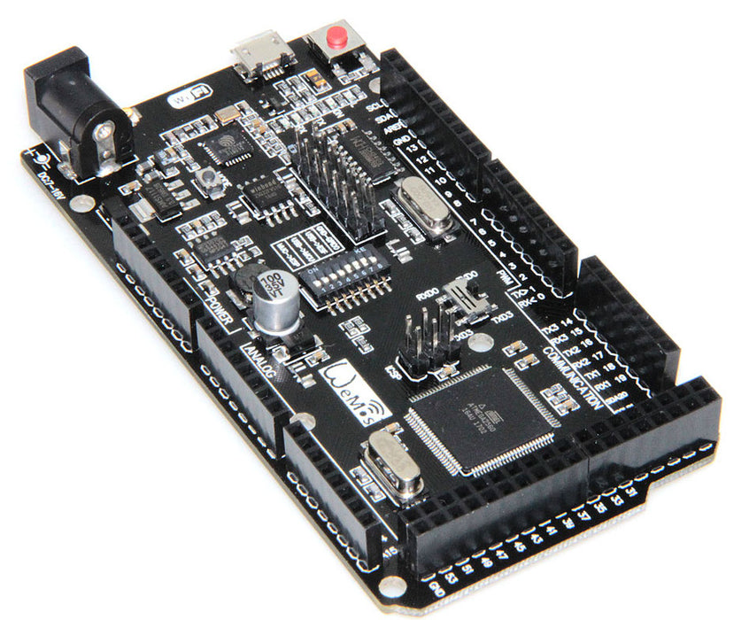
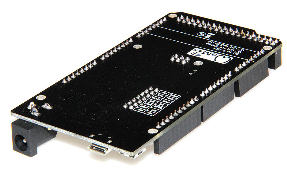
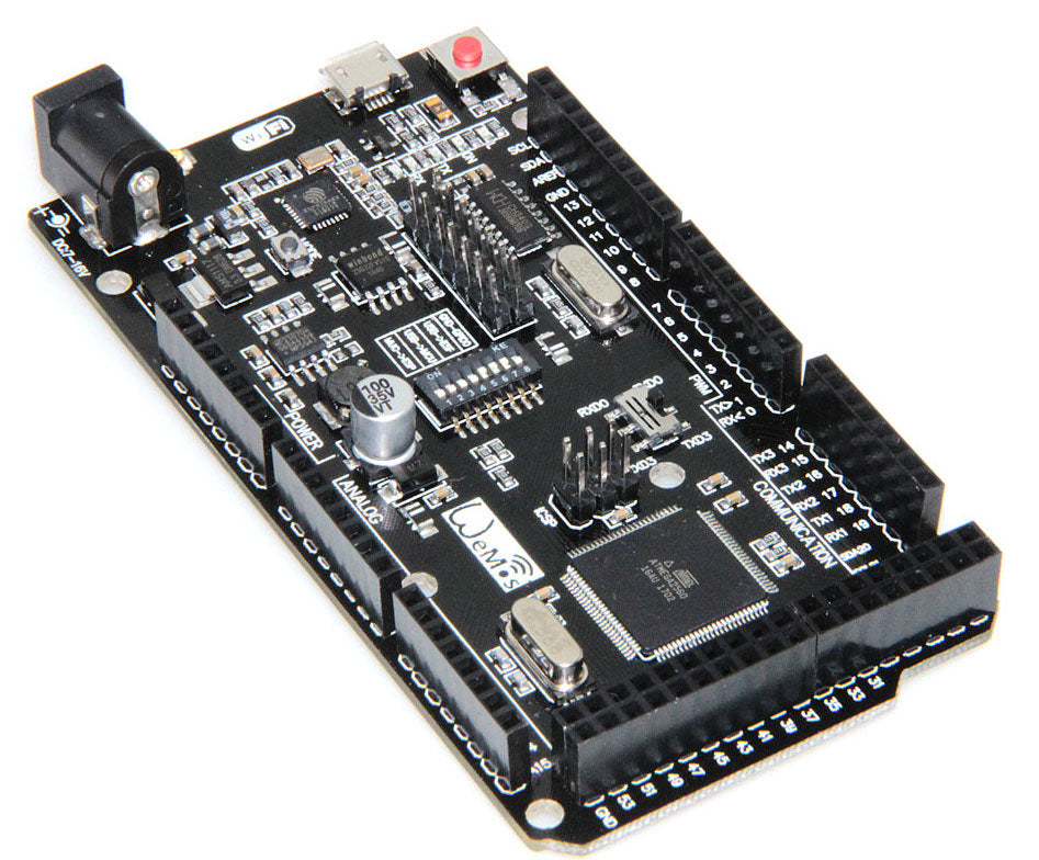
Arduino Mega 2560 R3 Compatible with ESP8266 WiFi MCU and 32 Mb flash memory
Need an Arduino Mega-compatible board that also has an ESP8266 WiFI microcontroller on board? Then order these value boards from PMD Way with free delivery.
Our Arduino Mega 2560-compatible is a microcontroller board based on the ATmega2560 (datasheet). It has 54 digital input/output pins (of which 14 can be used as PWM outputs), 16 analog inputs, 4 UARTs (hardware serial ports), a 16 MHz crystal oscillator, a USB connection, a power jack, an ICSP header, and a reset button.
It contains everything needed to support the microcontroller; simply connect it to a computer with your USB cable or power it with a AC-to-DC adapter or battery to get started. The Mega is compatible with most shields designed for the Arduino Duemilanove or Diecimila.
USB Drivers:
Click here for our CH34X USB driver download and installation guide.
Specifications:
| Microcontroller | ATmega2560 |
| Operating Voltage | 5V |
| Input Voltage (recommended) | 7-12V |
| Input Voltage (limits) | 6-20V |
| Digital I/O Pins | 54 (of which 14 provide PWM output) |
| Analog Input Pins | 16 |
| DC Current per I/O Pin | 40 mA |
| DC Current for 3.3V Pin | 50 mA |
| Flash Memory | 256 KB of which 8 KB used by bootloader |
| SRAM | 8 KB |
| EEPROM | 4 KB |
| Clock Speed |
16 MHz |
Techical details:
Click here for schematic .pdf
Click here for mechanical drawing
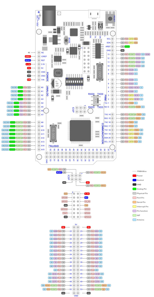
And now for the good stuff...
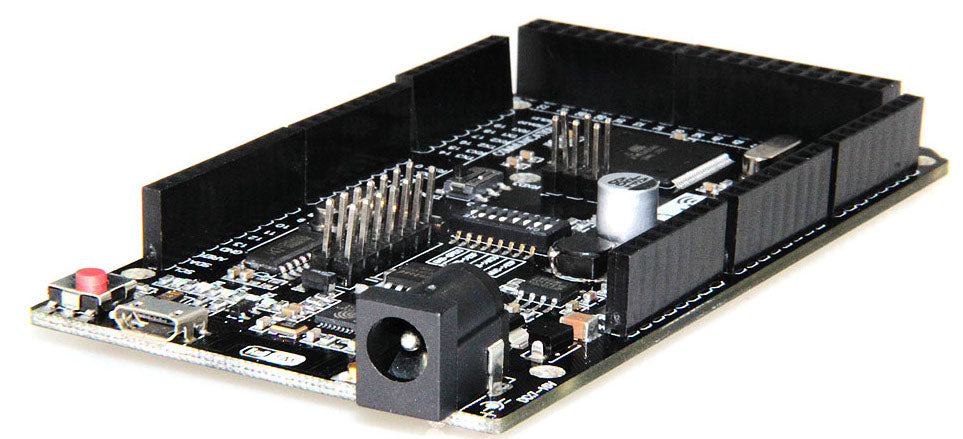
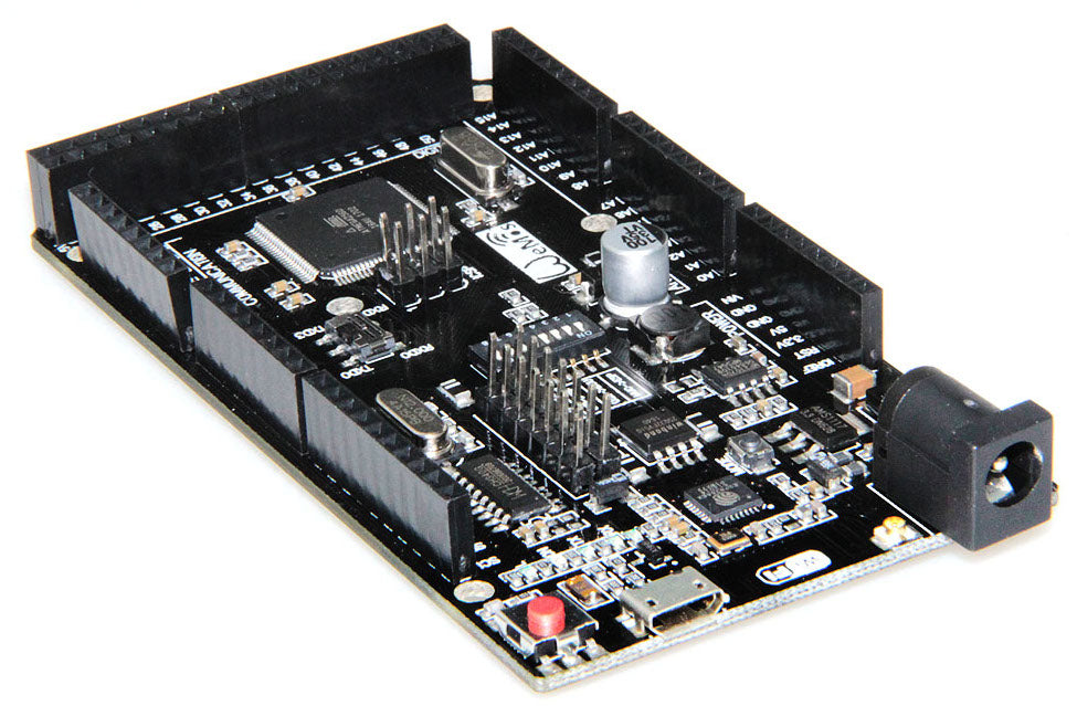
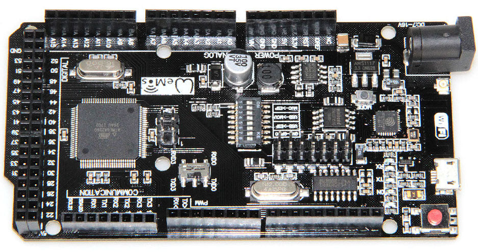
This Arduino Mega/ESP8266 hybrid board is a customized version of the classic Arduino Mega R3 board. This includes full integration of the Atmel ATmega2560 and the Wi-Fi ESP8266 with 8 MB flash memory ... and a USB-TTL converter based on the CH340G on one board. All modules can work together or independently.
Please take note of the following DIP switches on the board:
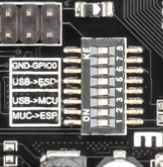
They are used to select the required mode of operation:
|
|
1 |
2 |
3 |
4 |
5 |
6 |
7 |
8 |
|
CH340 connect to ESP8266 (upload sketch) |
OFF |
OFF |
OFF |
OFF |
ON |
ON |
ON |
n/a |
|
CH340 connect to ESP8266 (connect) |
OFF |
OFF |
OFF |
OFF |
ON |
ON |
OFF |
n/a |
|
CH340 connect to ATmega2560 (upload sketch) |
OFF |
OFF |
ON |
ON |
OFF |
OFF |
OFF |
n/a |
|
CH340 connect to Mega2560 COM3 connect to ESP8266 |
ON |
ON |
ON |
ON |
OFF |
OFF |
OFF |
n/a |
|
Mega2560+ESP8266 |
ON |
ON |
OFF |
OFF |
OFF |
OFF |
OFF |
n/a |
|
All modules work independently of each other |
OFF |
OFF |
OFF |
OFF |
OFF |
OFF |
OFF |
n/a |
Also, have switch for change of connecting port between ATmega2560 and ESP8266:
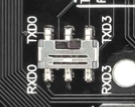
After choosing the mode of the board can proceed to set up the IDE
It is important that when the ESP8266 module is programming, it is necessary to press the button “Mode”
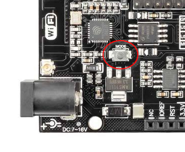
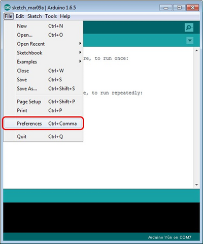
To begin open the Arduino IDE programming environment and go to settings
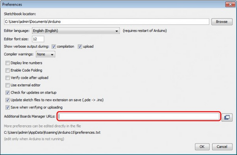
Then in the window that appears in the row, Additional Boards Manager URLs (marked in red) insert http://arduino.esp8266.com/stable/package_esp8266com_index.json link for installation in Arduino IDE additional scripts that would work with the modules ESP8266 and click OK
Then go to the Tools> Board> Boards Manager
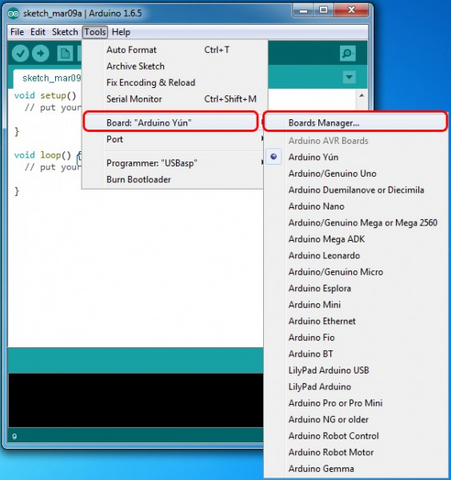
In the window that appears, scroll through the list down to the script esp8266 by ESP8266 Community and click.
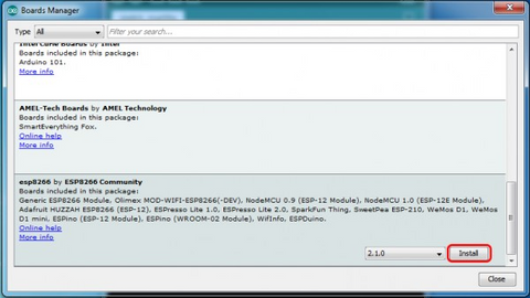
In the lower right corner will be able to select the version of the software, select the version 2.1.0 (the newest) and click the Install button
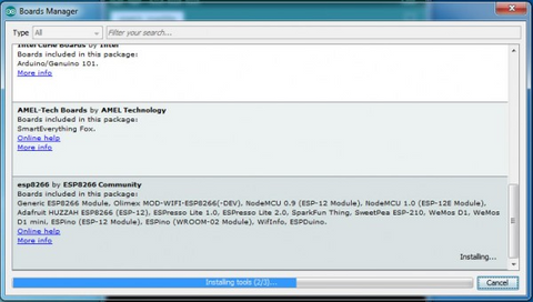
After installation, close the window and go to Tools> Board and see the list of available devices on the chip programming ESP8266
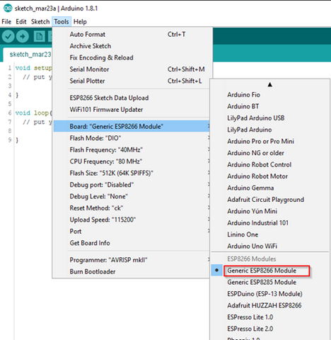
Next, you need to select the card as shown in the picture (Generic ESP8266 module)
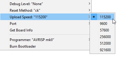
Select the upload speed - 115200
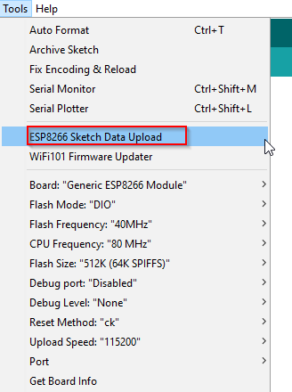
Test Arduino Sketch:
 void setup()

{

  Serial3.begin(115200);

  pinMode(13,OUTPUT);

  delay(500);

  Serial3.println("AT+CIPMUX=1");

  delay(2000);

  Serial3.println("AT+CIPSERVER=1,5000");

  delay(2000);

  Serial3.println("AT+CIPSTO=3600");

  delay(2000);

}


void loop()

{

   while(Serial3.available())

  {

    char Rdata;

    Rdata=Serial3.read();

    if(Rdata=='A'|Rdata=='a')

    {

      digitalWrite(13,HIGH);

      delay(50);

    }

    else if(Rdata=='B'|Rdata=='b')

    {

      digitalWrite(13,LOW);

      delay(10);

      digitalWrite(13,HIGH);

      delay(10);

      digitalWrite(13,LOW);

    }

    else

    {

      digitalWrite(13,LOW);

    }

  }


}
Don't forget to check out our full range of Arduino-compatible boards if this doesn't meet your needs. And as always, all orders receive free delivery.
And remember ... if you:
- can't find what you need
- not sure what to order
- want a bulk deal
- need technical support
- or just want to have a talk ...
Please email us via support@pmdway.com.
To keep up to date with new products, news, tutorials and more - we're on x, Facebook, Instagram, threads, reddit, and instructables.

