Raspberry Pi Pico Powers Oscilloscope with Smartphone Interface
from tomshardware.com
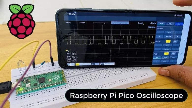
There's nothing worse than digging into a project only to realize the tool you need is nowhere to be found. But why buy something when you can whip up a solution from scratch using a Raspberry Pi? That's exactly what How To Electronics has done with this Raspberry Pi Pico-powered oscilloscope using a smartphone interface.
If you've never heard of them before, How To Electronics is a self-proclaimed electronics engineering community created by a team of electronics engineers. They regularly delve into projects and news involving a wide array of electronics including our favorite SBC, the Raspberry Pi. This week they've shared an exciting project we can't help but appreciate.
The project concept is simple and doesn't require much hardware to get started—especially if you already have spare Pis lying around. A Pico is programmed to detect frequencies using jumper wires and parses the data to a smartphone application for interpretation. For those unfamiliar, oscilloscopes are useful if you're tinkering with microelectronics, as they're used to test voltages and display the waveform data on a display in real-time.If we exclude hardware used for testing the configuration, all you need to create the oscilloscope is a Raspberry Pi Pico microcontroller, a micro USB cable, resistors and some male-to-male jumper wires.
The oscilloscope data is managed by an Android app called Scoopy on the software side. This logic analyzer acts as a visual interface for the oscilloscope input. According to How To Electronics, the setup can detect frequencies as high as 250KHz.
Take a look at the official project guide on the How To Electronics website to get an in-depth explanation behind how everything goes together and maybe even recreate the project yourself. How To Electronics provides plenty of information to get started and covers how to test your progress along the way.


Leave a comment