Using the TCA9548A 1-to-8 I2C Multiplexer Breakout with Arduino
Now and again you may find yourself needing to use more than one device with the same I2C bus address with your Arduino.
Such as four OLEDs for a large display - or seven temperature sensors that are wired across a chicken hatchling coop.
These types of problems can be solved with the TCA9548A 1-to-8 I2C Multiplexer Breakout, and in this guide we'll run through the how to make it happen with some example devices.
Getting Started
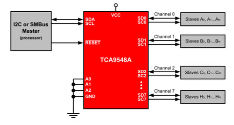
First, consider the TCA9548A itself. It is the gateway between your Arduino and eight separate I2C buses. You have a single bus on one side, connected to your Arduino.
On the other side of the TCA9548A, you have eight I2C buses, and only one of these can be connected to the Arduino at a time. For example (from the data sheet):
The TCA9548 can operate on voltages between 1.8 and 5V DC... and operate with devices that have operating voltages between 1.8 and 5V DC. This is very convenient, as (for example) you can use devices made for 3.3V operation with 5V Arduinos, or vice versa. Awesome. So let's get started.
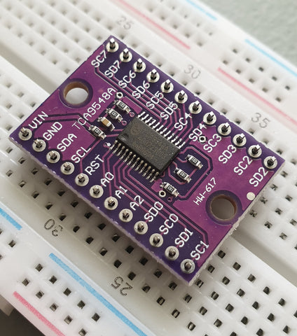
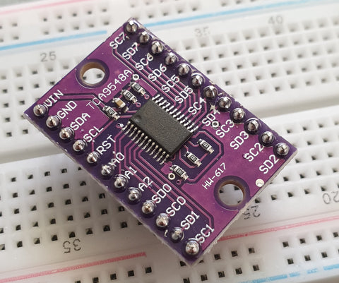
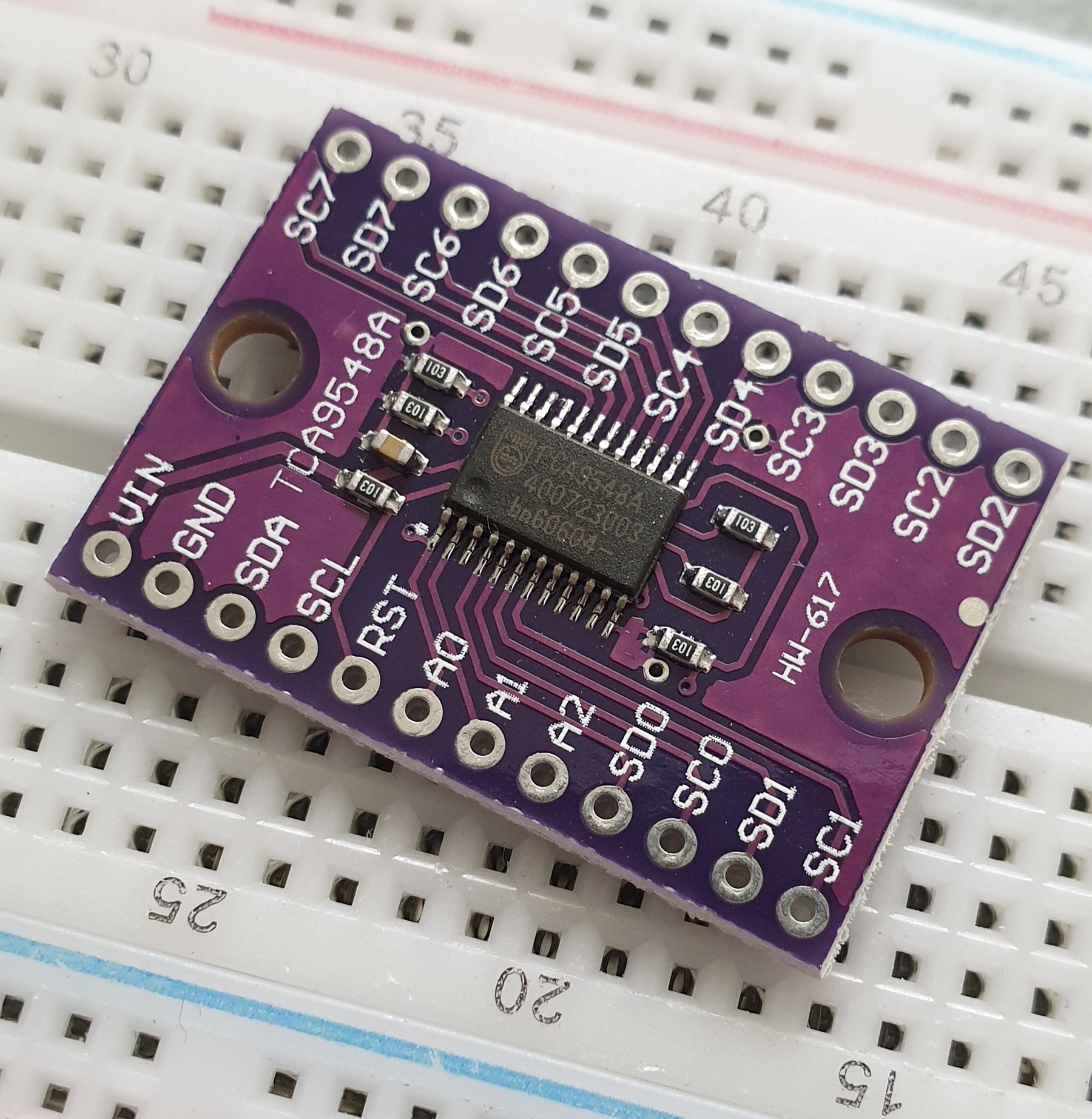
The breakout board includes inline header pins, which are not soldered to the board. So you need to do that. An easy way to line up the pins properly is to drop them into a soldereless breadboard, as such:
Then after a moment or two of soldering, you're ready to use:
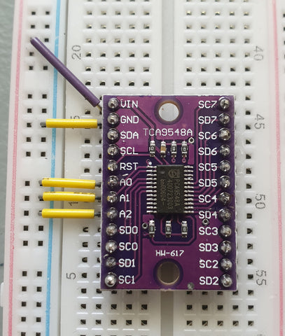
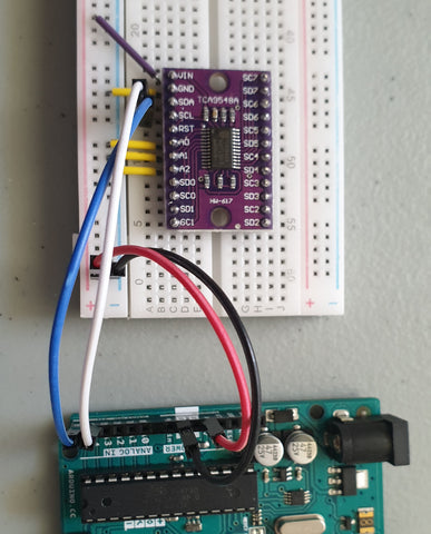
Next, insert your module into a solderless breadboard and wire it up as shown:
We are using the red and blue vertical strips on the breadboard as 5V and GND respectively. Finally, we connect the 5V and GND from the Arduino to the solderless breadboard, and A4/A5 to SDA/SCL respectively on the breakout board:
The electrical connections are as follows (Module --- Arduino):
- Vin to 5V
- GND to GND
- A0 to GND
- A1 to GND
- A2 to GND
- SDA to A4
- SCL to A5
Next, we consider the I2C bus address for the TCA9548A. Using the wiring setup shown above, the address is set to 0x70. You only need to change this if one of your other devices also has an address of 0x70, as shown in the next step.
Changing the I2C address of the TCA9548A
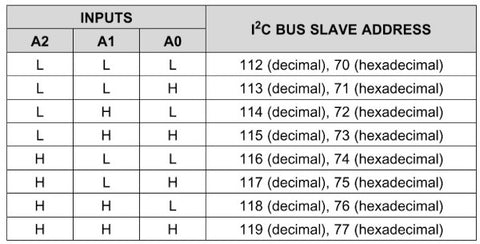
The bus address of the TCA9548A is changed using the connections to the A0, A1 and A2 pins. By default in the tutorial we use 0x70, by wiring A0~A2 to GND (known as LOW). Using the table below, you can reconfigure to an address between 0x70 and 0x77 by matching the inputs to HIGH (5V) or LOW (GND):
Testing
Before we get too excited, now is a good time to test our wiring to ensure the Arduino can communicate with the TCA9548A. We'll do this by running an I2C scanner sketch, which returns the bus address of a connected device.
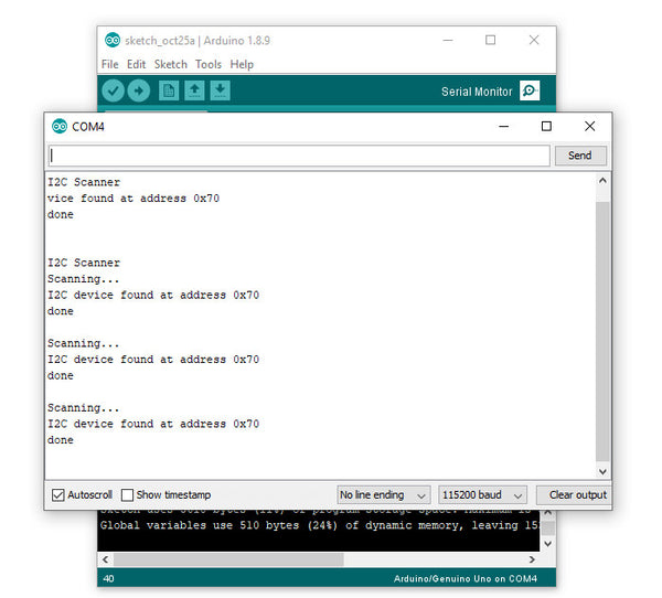
Copy and paste this sketch into your Arduino IDE and upload it to your board. Then, open the serial monitor and set the data rate to 115200. You should be presented with something like the following:
As you can see, our scanner returned an address of 0x70, which matches the wiring described in the bus address table mentioned earlier. If you did not find success, unplug the Arduino from the computer and double-check your wiring - then try again.
Controlling the bus selector
Using the TCA9548A is your sketch is not complex at all, it only requires one step before using your I2C device as normal. That extra step is to instruct the TCA9548A to use one of the eight buses that it controls.
To do this, we send a byte of data to the TCA9548A's bus register which represents which of the eight buses we want to use. Each bit of the byte is used to turn the bus on or off, with the MSB (most significant bit) for bus 7, and the LSB (least significant bit) for bus 0.
For example, if you sent:
0b00000001 (in binary) or 0 in decimal
... this would activate bus zero.
Or if you sent:
0b00010000 (in binary)
... this would activate bus five.
Once you select a bus, the TCA9548A channels all data in and out of the bus to the Arduino on the selected bus. You only need to send the bus selection data when you want to change buses. We'll demonstrate that later.
So to make life easier, we can use a little function to easily select the required bus:
void TCA9548A(uint8_t bus)
{
  Wire.beginTransmission(0x70);  // TCA9548A address is 0x70
  Wire.write(1 << bus);          // send byte to select bus
  Wire.endTransmission();
}
This function accepts a bus number and places a "1" in the TCA9548A's bus register matching our requirements. Then, you simply slip this function right before needing to access a device on a particular I2C bus. For example, a device on bus 0:
TCA9548A(0);
... or a device on bus 6:
TCA9548A(6);
A quick note about pull-up resistors
You still need to use pull-up resistors on the eight I2C buses eminating from the TCA9548A. If you're using an assembled module, such as our example devices - they will have the resistors - so don't panic.
If not, check the data sheets for your devices to determine the appropriate pull-up resistors value. If this information isn't available, try 10k0 resistors.
Controlling our first device
Our first example device is the tiny 0.49" OLED display. It is has four connections, which are wired as follows (OLED --- TCA9548A/Arduino):
- GND to GND
- Vcc to Arduino 3.3V
- CL to TCA9548A SC0 (bus #0, clock pin)
- DA to TCA9548A SD1 (bus #0, data pin)
The OLED runs from 3.3V, so that's why we're powering it directly from the Arduino's 3.3V pin.
Now, copy and upload this sketch to your Arduino, and after a moment the OLED will display some numbers counting down in various amounts:
So how did that work? We inserted out bus selection function at line 9 of the sketch, then called the function in at line 26 to tell the TCA9548A that we wanted to use I2C bus zero. Then the rest of the sketch used the OLED as normal.
Controlling two devices
Let's add another device, a BMP180 barometric pressure sensor module. We'll connect this to I2C bus number seven on the TCA5948A. There are four connections, which are wired as follows (BMP180 --- TCA9548A/Arduino):
- GND to GND
- Vcc to Arduino 3.3V
- CL to TCA9548A SC0 (bus #7, clock pin)
- DA to TCA9548A SD1 (bus #7, data pin)
Now, copy and upload this sketch to the Arduino, and after a moment the OLED will display the ambient temperature from the BMP180 in whole degrees Celsius. This is demonstrated in the following video (finger is placed on the BMP180 for force a rise in temperature):
So how did that work? We set up the libraries and required code for the OLED, BMP180 and TCA5948A as usual.
We need to intialise the BMP180, so this is done at line 29 - where we select the I2C bus 7 before initiating the BMP180.
The the sketch operates. On line 40 we again request I2C bus 7 from the TCA9548A, then get the temperature from the BMP180.
On line 44 we request I2C bus 0 from the TCA9548A, and then display the temperature on the OLED. Then repeat.
A quick note about the reset pin
More advanced users will be happy to know they can reset the TCA9548A status, to recover from a bus-fault condition. To do this, simply drop the RESET pin LOW (that is, connect it to GND).
Where to from here?
You can now understand through our worked example how easy it is to use the TCA9548A and access eight secondary I2C buses through the one bus from your Arduino. Don't forget that the TCA9548A also does double-duty as a level converter, thereby increasing its value to you.
If you've got your TCA9548A and not finding success, you can always email support@pmdway.com for assistance.

